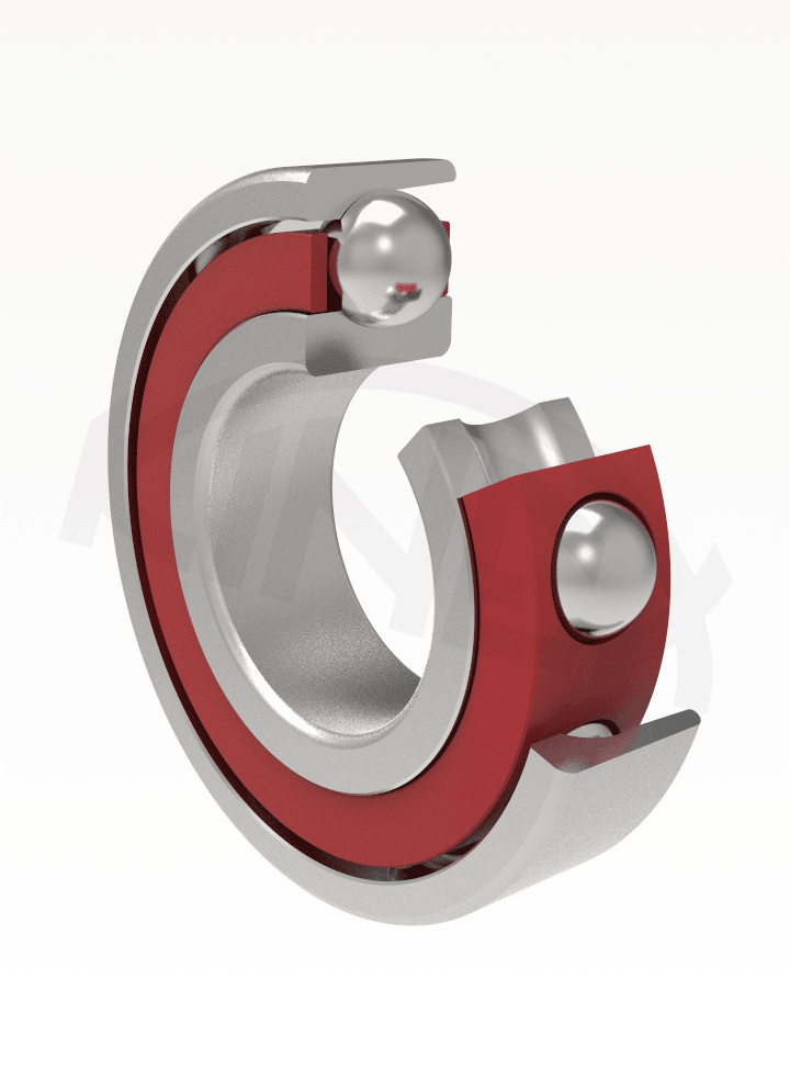
Single-row angular contact ball bearings for high rotation frequency and high accuracy of seating differ from normal angular contact ball bearings by inner design of bearing rings, by value of contact angle between ball and normal raceways of rings, by workmanship of cage and by high precise tolerance class of running.
The bearings are non-separable and their suitable seating arrangement assures required firmness and accuracy of housing. Bearings with ceramic balls are manufactured for extreme high speed with requirements for low friction and low heat generation in bearing, which gives less lubrication demands and higher lifetime of seating.
KINEX BEARINGS, a.s. delivers the single-row ball bearings with contact angles of α = 10°, α = 12°, α = 15°, α = 25° and α = 26°.
The bearings have special textile cage guided by inner ring (TB) or by outer ring (TA). Part of assortment has the massive brass cage guided by inner ring MB. Bearings with contact angle of α = 10° (designation B72.. CBTB and B72.. CBTA) have been designed for shaft support in grinding electro-spindles. The bearings are manufactured in tolerance class P4 according to the STN ISO 492, or in tightened tolerance class P4A (bearings of the P4A tolerance had been formerly delivered with additional TPF 1148 designation).
The bearings with contact angle of α = 12° (designation B70... CATB and B72.. CATB) and those with α = 26° (designation B70... AATB and B72.. AATB) have been designed for rotation seating of spindles and headstocks of tool machines and similar high-speed machines that require high accuracy of seating. The bearings are normally manufactured in tolerance classes P5 and P4 in accordance with the STN ISO 492.
The bearings with contact angle of α = 15° (designation B70... CTA, C B70.. CTA and C B72.. CTA) and α = 25° (designation B70...ATA, C B70..ATA and C B72..ATA) have the cage guided by asymmetric outer ring and they are manufactured in tolerance classes P5 and P4A.
This range assures the wide scope of products in terms of functional parameters of product and its seating. Products with contact angle of α = 10°, α = 12° and α = 26° were formerly designed for specific seating and they can also be used in new seating provided that the product design and its functional parameters listed in dimension tables meet requirement of seating, first of all in terms of lubrication of bearings
The boundary dimensions of bearings listed in dimension tables meet the international dimensional plan ISO 15.
Designation of bearings of basic workmanship is listed in dimensional tables. Modification of basic type is designated by additional symbols according to the STN 02 4608. Meaning of individual signs for single-row angular contact ball bearings is specified in designation scheme. The values ΔDmp and Δdmp are indicated on rings and on outer package at bearings manufactured in tolerance classes P4, P4A and P2 and at universal matched bearings.
ΔDmp - deviation of middle outer diameter in single radial plane,
Δdmp - deviation of middle bore diameter in single radial plane.
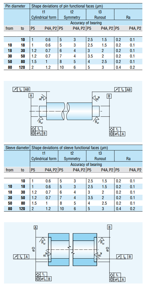
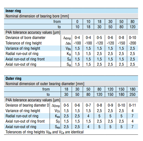
The single-row angular contact ball bearings are normally manufactured in tolerance classes P5, P4 and P2 according to the STN ISO 492. Tolerances of dimensions and deviations from geometry of functional surfaces for bearings manufactured in tolerance P4A are listed in following table:
Inner clearance in a bearing must assure the required contact angle between balls and raceways of rings.
High-grade pure and re-melted bearing steel is used for production of rings and steel balls.
Ceramic balls are made of material Si3N4.
Single-row angular contact ball bearings intended for high-speed rotation are delivered as single or paired mounting.
Individual systems of pair mounting are as follows:
1. Back-to-back arrangement (O)
This pair is characterised by strong firmness with respect to tilt and can transfer axial forces in both directions. But these forces are always absorbed by one bearing only. The pair is suitable for elimination of tilt moments.
2. Face-to-face arrangement (X)
This pair is characterised by a bit lesser tilt firmness as in case of "O" arrangement and it can transfer axial forces in both directions. But these forces are always absorbed by one bearing only.
3. Tandem arrangement (T)
This pair is characterised by strong firmness and it is suitable for absorbing of axial forces acting in one direction.
4. Universal arrangement (U)
These bearings are normally arranged in paired mounting "O", "X" and "T". They are manufactured with slight preload (UL) or with middle preload (UM). The bearings are delivered in packing by singles or by pairs. Other packing ways can be agreed with producer of bearings.
Paired mounting of bearings is delivered in one package. Bearings of different pairs can not be interchanged. The spot of most radial runout of ring is marked by line on the front faces. Mutual position of bearings or the sequence of paired bearings is marked by convergent lines of "V" shape on outer roller faces of paired mounting. Bearings are assembled in pairs into seating in such manner that the lines, marking the spot of most radial runout of appropriate rings (inner or outer), must be parallel-aligned with the axis of shaft. Marking of most radial runout serves for minimisation of effects of radial runout of seating faces.
Paired mounting of bearings, arranged in "O" or "X" are delivered with low (L), middle (M) or high (S) axial preload. Universal paired bearings, packed by two pieces (DUL) are interchangeable and they are not marked by arrow on the face.
Values of axial preload Fp for arrangement of bearings are listed in dimension tables. Values of dynamic basic load rating Cr and static basic load rating Cor for single bearing are listed in dimension tables.
Basic radial dynamic load rating of matched bearings within the group: Crs = Cr . i 0,7
Basic radial static load rating of matched bearings within the group: Cors = Cr . i
where:
Cr a Cor – are values of radial basic load ratings in kN of relevant bearing listed in dimension tables,
i – number of matched bearings within the group
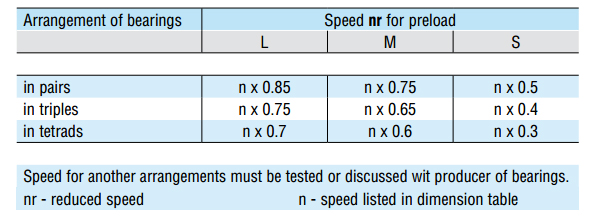
Operational revolutions of seating are also given, besides bearing construction and its workmanship accuracy, by number of bearings and their arrangement, and by energetic, power and geometric parameters of seating. Pilot values of limit speed for single bearing are listed in dimension tables. Recommended speed for paired mounting are listed in following table: For pairs arranged in "X" at greater mutual distance of bearings there is necessary to take account of slight speed reduction; for pairs arranged in "OT" there is assumption of slight increase of speed.
Single-row angular contact ball bearings are delivered arranged in triples or tetrads in special cases of precise seating with requirements for higher strength parameters of seating. Examples of most frequent ways of arrangements are shown in following picture:
Bearings with contact angle α = 25° a α = 26° (A a AA)
Single bearings arranged in "T" pair
Pr = Fr for Fa/Fr ≤ 0,68
Pr = 0,41Fr + 0,87Fa for Fa/Fr > 0,68
Bearings with contact angle α = 25° a α = 26°
Single bearings and pairs arranged in „T“
Por = 0,5Fr + 0,37Fa (Por ≥ Fr)
Paired mounting arranged in do „O“ and „X“
Por = Fr + 0,74Fa
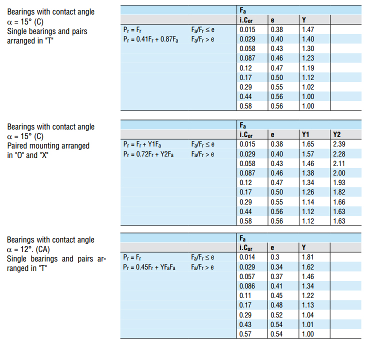
Bearings with contact angle α = 15°
Single bearings and pairs arranged in „T“
Por = 0,5Fr + 0,46Fa (Por ≥ Fr)
Paired mounting arranged in do „O“ and „X“
Por = Fr + 0,92Fa
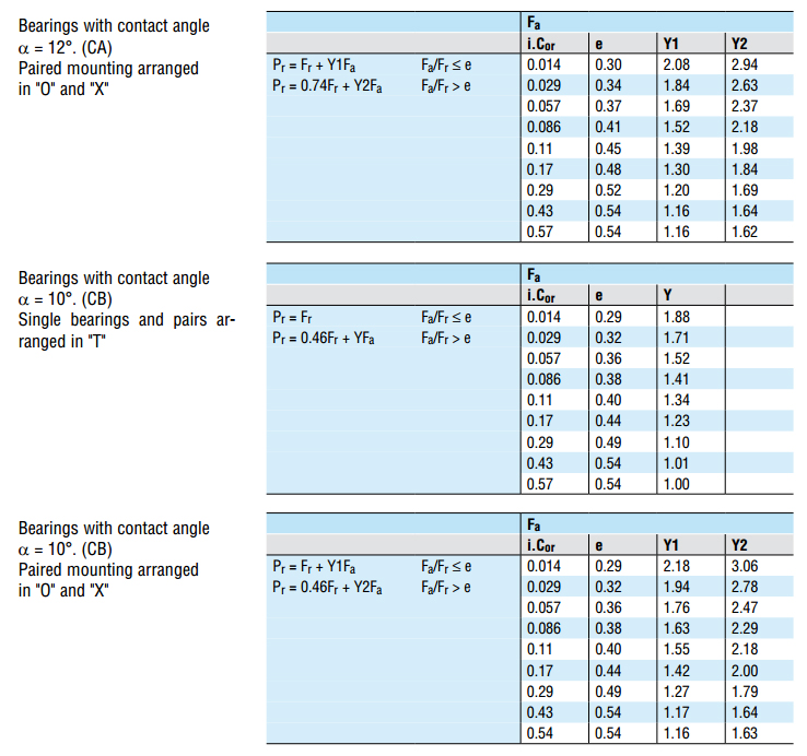
Bearings with contact angle α = 12°
Single bearings and pairs arranged in „T“
Por = 0,5Fr + 0,47Fa (Por ≥ Fr)
Paired mounting arranged in do „O“ and „X“
Por = Fr + 0,94Fa
Bearings with contact angle α = 10°
Single bearings and pairs arranged in „T“
Por = 0,6Fr + 0,5Fa (Por ≥ Fr)
Paired mounting arranged in do „O“ and „X“
Por = Fr + 0,97Fa
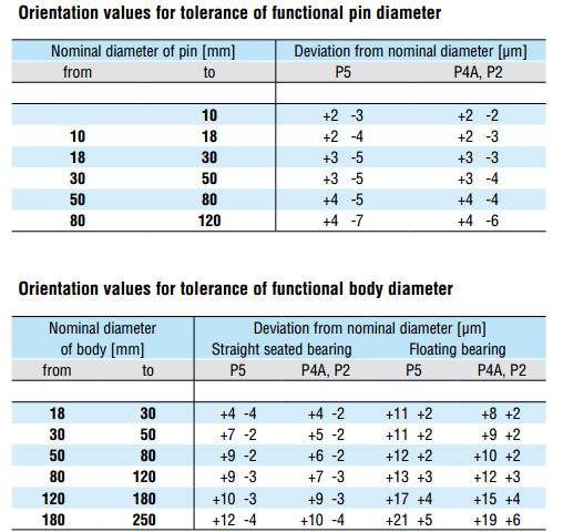
Usage of parameters of high-precise single-row angular contact ball bearings is possible only while the seating functional faces have comparable parameters. Tested and recommended tolerances and accuracy values of seating functional faces are listed in following tables.