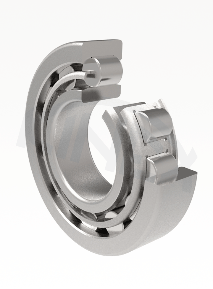
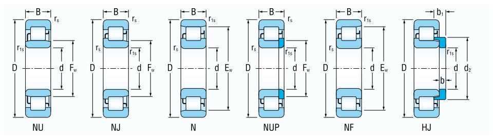
Single-row cylindrical roller bearings are made in several designs.
The NU design has rollers guided between ribs on the outer ring, while the N design has rollers guided between ribs on the inner ring. Both designs allow axial shift of the rings in both directions.
The NJ design is constructed with two guiding ribs on the outer ring and one on the inner ring.
The NF design is made with two guiding ribs on the inner ring and one on the outer ring. Both designs allow transmission of a limited axial force in one direction.
Besides the elements used in the NJ design, the NUP design has an additional flat ring, functioning as the second supporting head on the inner ring and allows the bearing to transfer limited axial forces in both directions.
Axial guiding in both directions can be achieved by using HJ angle rings for NJ design bearings and axial guiding in one direction for NU design bearings. Designation of the shaped angle ring belonging to individual bearings with tapered hole are stated in dimension tables.
Single-row cylindrical roller bearings have higher load-bearing capacity than single-row ball bearings of the same size, and are suitable for mounting with high radial load, high rotational frequency and where fixed mounting of both rings is required.
The basic dimensions of single-row cylindrical roller bearings stated in dimension charts comply with the international dimension plan ISO 15.
Identification of the basic design bearings is provided in the table part of the publication. Deviations from the basic designs are indicated by additional symbols in accordance with STN 02 4608. The meaning of the most commonly used symbols is provided in the following table:
| Symbol | Example of designation | Meaning |
| R | R NU205 | Bearing without one (separable) ring |
| L | LNU206 | Removable ring of separable bearing |
| C3 | NJ311 C3 | Radial clearance greater than normal |
| R... | NU210 R70-90 | Radial clearance in non-standardized range (range in µm) |
| E | NU2209E | Modification of internal design, higher load rating |
| M | NJ219M | Solid brass cage connected by rivets |
| M1 | NJ207EM1 | Solid brass cage connected without rivets |
| TNG | NIJ306ETNG | Solid polyamide cage centered on cylindrical roller |
| N | NU207N | Snap ring groove on outer ring |
| NR | NU206NR | Snap ring groove on outer ring and inserted snap ring |
| P6 | NU217 P6 | Tolerance class higher than normal |
| S0 | NU220 C3S0 | Stabilization for operation at temperature up to 150 °C |
| S1 | NU220 C3S1 | Stabilization for operation at temperature up to 200 °C |
| S2 | NU220 C3S2 | Stabilization for operation at temperature up to 250 °C |
Single-row roller bearings are made with a sheet-metal steel cage guided on rollers, which is not marked.
Bearings for special mounting applications are made with plastic or brass cages.
The additional symbol for plastic cages, TNG means that the cage is made as a single part from polyamide PA 6.6., reinforced with 25% of glass fibre.
Brass cages are manufactured in two designs – M with the brass cage joint with steel rivets and M1 with the cage flange and body joint with pressed-out legs.
If the brass cage is to be guided on the outer MA ring or the inner MB ring, the delivery of bearings must be discussed in advance.
Bearings are commonly produced in normal tolerance class P0 which is not indicated. Bearings for more demanding arrangements are delivered in tolerance classes P6, P5 and P4.
Commonly produced bearings have normal radial clearance which is not indicated. For special arrangements bearings with smaller clearance C2 or greater radial clearance C3, C4 and C5 are delivered.
The symbols for a tolerance class and radial clearance are grouped together in the basic designation, e. g.:
P6 + C3 = P63
P6 + C4 = P64, etc.
Angle rings – type HJ2, HJ2E, HJ3, HJ3E and HJ4 can be used for bearings in NJ and NU designs.
Examples of bearing designation:
NJ2 + HJ2 = NH2
NJ3 + HJ3 = NH3
NJ4 + HJ4 = NH4
NU2 + HJ2 = NUJ2
NU3 + HJ3 = NUJ3
NU4 + HJ4 = NUJ4
Single row cylindrical roller bearings without inner ring designated R NU are delivered for arrangements with limited space for bearing mounting.
The hardened and grinded pin is the inner bearing ring raceway. Dimension tolerance on the pin is usually “g6” for normal radial clearance, “f6” for greater radial clearance and “h5” for smaller radial clearance. Ovality and cylindricity deviations of the “raceway” on this pin can not be greater than deviations for tolerance class IT3. Surface roughness for this surface should be Ra = 0.2 and for less demanding arrangements Ra = 0.4.
Basic load rating Cr and Cor values shown in the dimension tables, are valid for bearings RNU if the pin surface hardness will be in the range 59 to 65 HRC. With decreasing hardness value, the load rating values Cr decreases as well. It must be multiplied by the factor fh from the following table. Minimum depth of pin hardening after grinding depends on the cylindrical roller diameter and load magnitude and should be 1 to 3mm.
| Hardness HRC | 58 | 56 | 54 | 51 | 48 | 45 | 40 | 35 | 30 |
| Factor fh | 0,9 | 0,8 | 0,7 | 0,6 | 0,5 | 0,4 | 0,3 | 0,25 | 0,2 |
Mutual bearing ring misalignment of single row cylindrical roller bearings is very small. Permissible misalignment values are in the table.
Bearing type Load
light (Fr<0,1Cor) heavy (Fr>=0,1Cor)
NU10, NU2, NU3, NU4 2'-3' 5'-7'
NU22, NU23 1'-3' 3'-4'
Designs NJ, NUP, N (*1)
of all dimension series 1'-2' 3'-4'
1) Smaller values of the number pair are valid for bearings of width series 2 and higher
The dynamic load for single-row cylindrical roller bearings with radial load only and without axial forces is calculated according to the following formula:
Pr = Fr [kN]
If roller bearings are also used to transmit axial forces, the dynamic load is calculated according to the following formula:
Pr = Fr for Fa/Fr ≤ e
Pr = 0,92 Fr + Y. Fa for Fa/Fr > e
where
e = calculation coefficient
e = 0,2 for 2, 3, 4 grade roller bearings
e = 0,3 for 22, 23 grade roller bearings
Y = axial load coefficient
Y = 0,6 for 2, 3, 4 grade roller bearings
Y = 0,4 for 22, 23 grade roller bearings
To ensure reliable operation of cylindrical roller bearings transmitting axial load, simultaneous load with a radial force must be ensured and the ratio Fa/Fr should not be greater than 0.5.
The following applies for cylindrical roller bearings under static load:
Por = Fr [kN]


