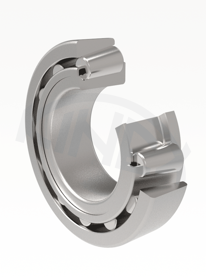
The single row tapered roller bearings have one row of tapered rollers resting on the guiding rib of the inner ring with their functional faces. Due to the great number of tapered rollers, these bearings have a high load rating capacity in the radial as well as axial directions. The axial load carrying capacity depends on the contact angle magnitude. The arrangement with single row tapered roller bearings is usually formed by a bearing pair. A single bearing can carry the axial load only in one direction. The bearings are separable. The inner ring (cone) with tapered rollers and a cage is one assembly unit. The outer ring (cup) is the other assembly unit. The single row tapered roller bearings are manufactured in metric dimensions as well as in inch dimensions.
The boundary dimensions of metric single row tapered roller bearings indicated in the dimension tables correspond to the international dimensional standard ISO 355.
The boundary dimensions of inch single row tapered roller bearings indicated in the dimension tables correspond to the American standard AFBMA Standard 19.2 (USA).
The designation of standard design bearings is given in the table part of this publication. The additional mark X used on the 320 series bearings means, that the main dimensions are changed in accordance with the recommendations of the international standards ISO.
The single row tapered roller bearings are equipped with a pressed steel cage which is not marked.
The bearings are commonly produced in normal tolerance class P0 which is not indicated.
The single row tapered roller bearings are usually mounted in pairs, in which required clearance, or preload are adjusted when mounting. Clearance or preload magnitude is determined according to the requirements on arrangements.
The seating surfaces for single row tapered roller bearings must be coaxial, aligned only with small deviations, because the admissible ring misalignment is very small. Under common operating conditions the misalignment is
under light load (Fr < 0,1Cor) 1’ to 1,5’
under heavy load (Fr ≥ 0,1Cor) 2’ to 4’.
The calculation methods are defined in the STN ISO 281 (dynamic load) and STN ISO 76 (static load) norm.