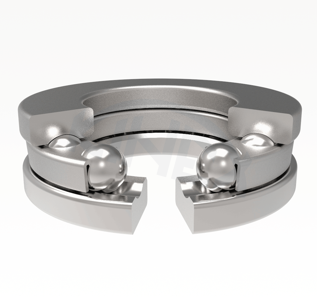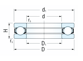
The single direction thrust ball bearings consist of two washers with raceways for one row of balls with a cage. The washers have flat seating surfaces. They must be supported in order to spread the load on the balls evenly. These bearings are designed to carry axial forces acting in one direction only. They cannot carry radial forces.

The boundary dimensions of the thrust ball bearings indicated in the dimension tables correspond to the international dimensional plan ISO 104.
The designation of the bearings in the basic design is indicated in the dimension tables. The differences from the basic design are designated by additional symbols in accordance with the STN 02 4608.
The thrust ball bearings have strip steel cages which are not marked. For special applications, some bearings types are available with a machined brass cage (M). Bearings with these cages are only made to order.
Thrust ball bearings are usually produced in normal tolerance class P0 (symbol P0 is not shown). In special cases of arrangement, demanding higher accuracy, bearings are produced in higher tolerance classes P6. Tolerances of accuracy, deviations of dimensions and operation are stated in ISO STN 199.
The thrust ball bearings require as accurate alignment of seating surfaces as possible. Any misalignment causes increased stress between the rolling elements and raceways contact. Therefore, the thrust ball bearings are not suitable for carrying forces under misalignment of the shaft and housing washers.
Axial Equivalent Dynamic Load
Pa = Fa [kN]
Minimum Axial Load
When using the thrust ball bearings under higher rotational speeds, the sliding of the balls between the ring raceways due to centrifugal forces can occur if the axial load Fa drops below a certain minimum value determined from the following equation:

where:
Fa min – minimum axial load [kN]
nmax – maximum rotational speed [min-1]
M – minimum axial load factor (values are indicated in the dimension tables)
If the external axial load is low (lower than Fa min) or if the bearing is relieved during the operation, such as when one row of balls in the double direction thrust ball bearings or one bearing in the arrangement of a single direction bearing pair is relieved, it is necessary to secure the minimum axial load, e.g. using springs.
Axial Equivalent Static Load
Poa = Fa [kN]