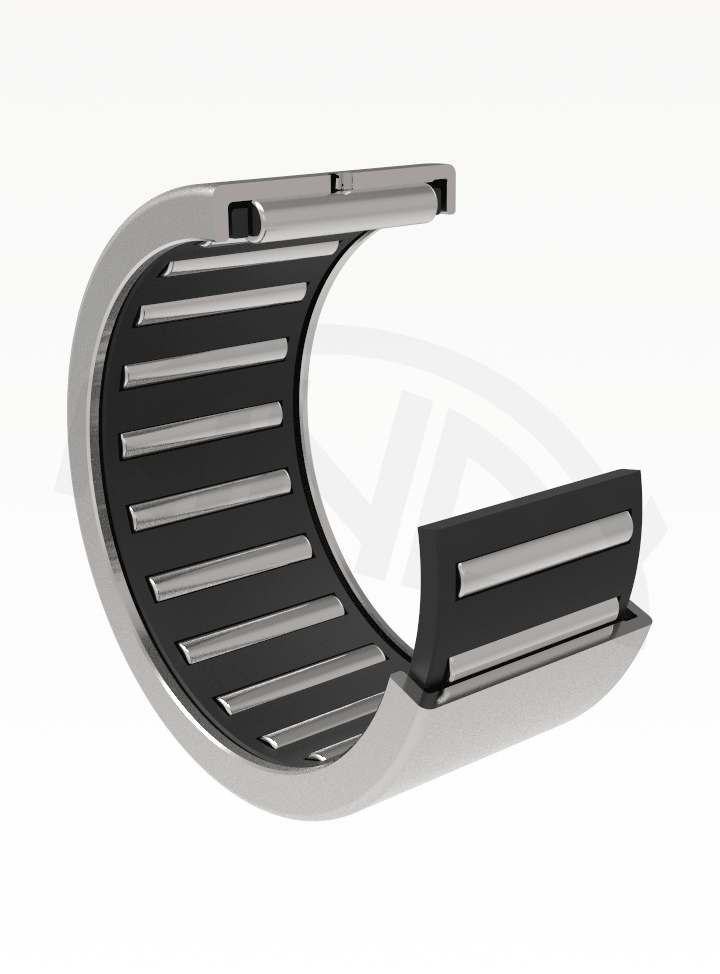
Opened and closed drawn cup needle roller bearings are needle roller bearings with the smallest radial construction height consisting of a thin walled non-cutting outer rings and needle cages. Cage with needles allows rolling placing with high load capacity and also provides excellent function of the bearing even at high speeds and long lubrication intervals thanks to the large spaces for grease.
These drawn cup needle roller bearings, if not placed directly on the hardened shafts, may be combined with inner rings LR or IR. Inner rings belonging to specific bearings are indicated in the dimension tables.
Drawn cup needle roller bearings are supplied in these design:
In comparison with opened drawn cup needle roller bearings the closed drawn cup needle roller bearings type do have closed bottoms and are suitable to close the placing at the end of the shaft and to capture the start-up forces.

Main dimensions of drawn cup needle roller bearings opened and drawn cup needle roller bearings closed, which are given by the dimensional tables, correspond to the international dimensional plan of ISO 3245.
Designation of drawn cup needle roller bearings opened and drawn cup needle roller bearings closed in the main realization is given in dimensional tables.
Drawn cup needle roller bearings have steel cages, which are not specifically indicated. The smallest sizes and bearings for special applications are made with polyamide cages indicated by the added letters TV.
Sealed drawn cup needle roller bearings have seals with a latch protecting the bearing from contaminants and retaining plastic lubricants under the normal operating conditions. They can be used under temperatures ranging from −30°C to +100°C. These bearings are always supplied filled with a suitable plastic lubricant.
The main dimensions and specification of drawn cup needle roller bearings in the RS and -2RS design are listed in the dimension tables.
Thin walled outer rings of opened and closed drawn cup needle roller bearings made by non-cutting mechanical working become their final dimensional and shape accuracy only after being pressed into the body housing. Dimensional and shape accuracy of the hole is given by the position of shell circle and quality of placing when assembled. When respecting the tolerances of bodies given in the table, the shell circle of needle rollers at solid bodies in the tolerance field F8 gives with given tolerances of the shaft the normal operational clearance.
| Material of the body (solid body) |
Tolerance of the hole |
Tolerance of the shaft without inner ring |
with inner ring |
| steel or cast iron | N6 (N7) | h5 (h6) | k5 (j6) |
| light metal | R6 (R7) |
In case of less solid bodies there is a need to test and define by which tolerance of the shaft the required radial tolerance will be reached with. Accuracy of shape of hole in the body must in IT 5 limits. Deviations of width of the opened and closed drawn cup needle roller bearings are -0,2 mm..
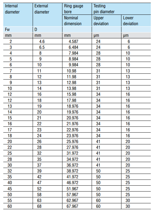
Checking of dimensions of drawn cup needle roller bearings in not pressed state is not possible as the thin-walled ring may be imperfectly circular due to the production technology. Only after pressing into the hole of the body with recommended tolerances the bearing obtains its accuracy for its proper operation.
Dimensions can be checked as follows:

The admissible misalignment for drawn cup needle roller bearings fitted directly on tempered shafts or combined with inner LR or IR inner rings is very small. The admissible misalignment is up to 2´. The admissible misalignment depends on the internal bearing design, radial clearence during operation, and the forces and torque transmitted by the bearing. The quoted value is therefore approximate.
Dynamic equivalent radial load
Pr = Fr
Static equivalent radial load
Por = Fr